Simple Mechanism Prototype
Crank and slotted lever mechanism
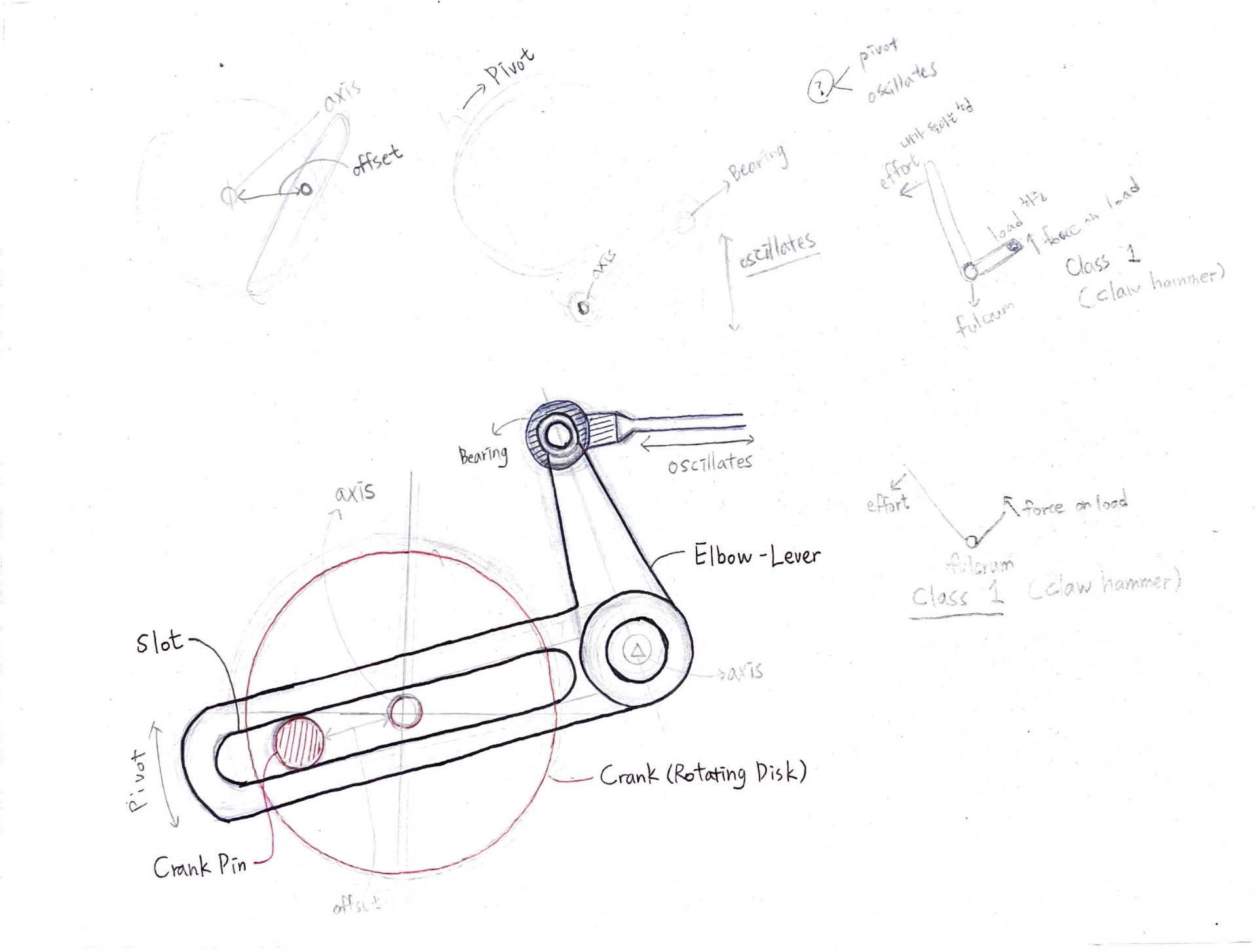
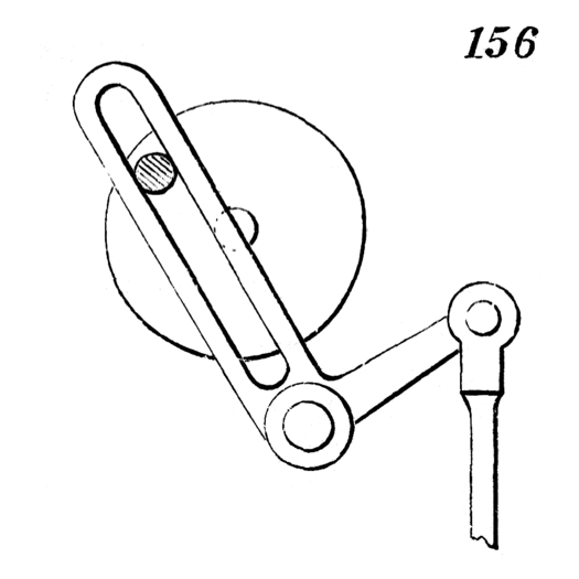
Components
- Crank (Rotating Disk):
The large circular disk that rotates. It contains a pin or wrist pin attached at some offset from the center. - Crank Pin/Wrist Pin:
A small pin attached to the rotating disk. It moves in a circular path as the disk rotates. - Slot (in the Bell-Crank/Elbow-Lever):
A slot in the lever (bell-crank or elbow-lever), where the crank pin moves back and forth, allowing for variable rectilinear motion. - Bell-Crank/Elbow-Lever:
A pivoting lever that moves based on the motion of the crank pin within its slot, converting circular motion from the disk into alternating linear motion.
Motion Transfer Between Components
- The crank (rotating disk) rotates around its axis.
- The crank pin moves in a circular motion due to being offset from the center of the disk.
- The crank pin is positioned in the slot of the bell-crank or elbow-lever, which guides its motion along the slot.
- As the crank pin moves through the slot, it causes the bell-crank/elbow-lever to pivot back and forth, converting the circular motion of the disk into alternating rectilinear motion.
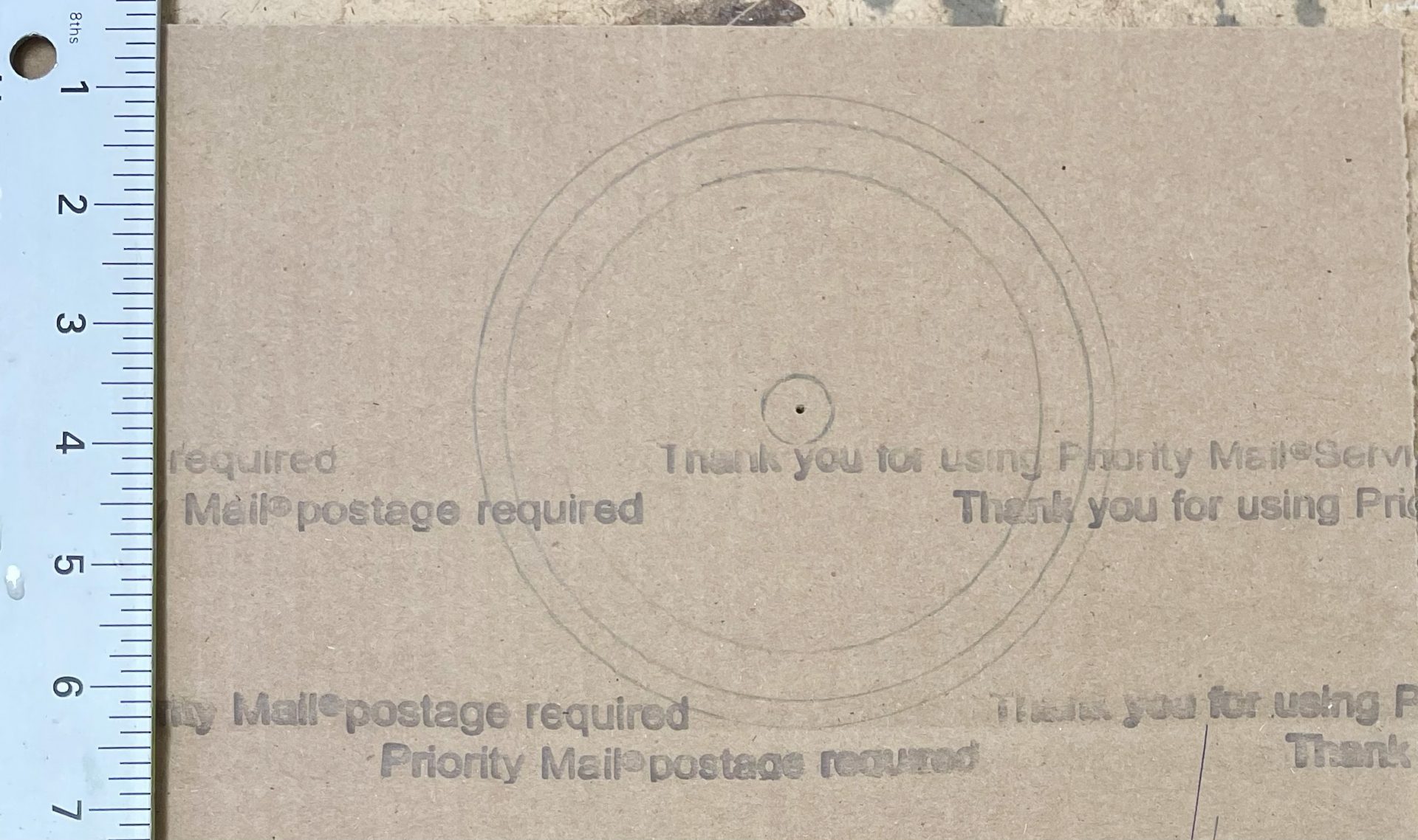
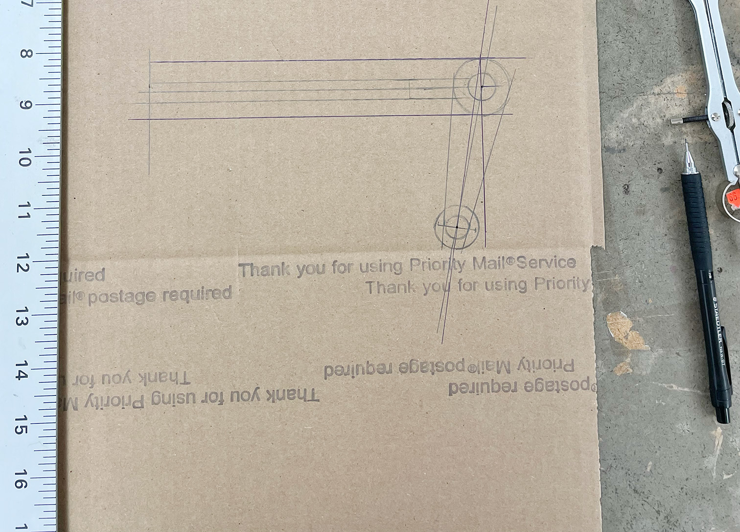
Process
I used cardboard to make the components. For the axis and bearing parts, I experimented with different sizes of bolts and nuts.
The inside of the slot is the rough side of the cardboard, so I covered it with black tape to reduce friction.
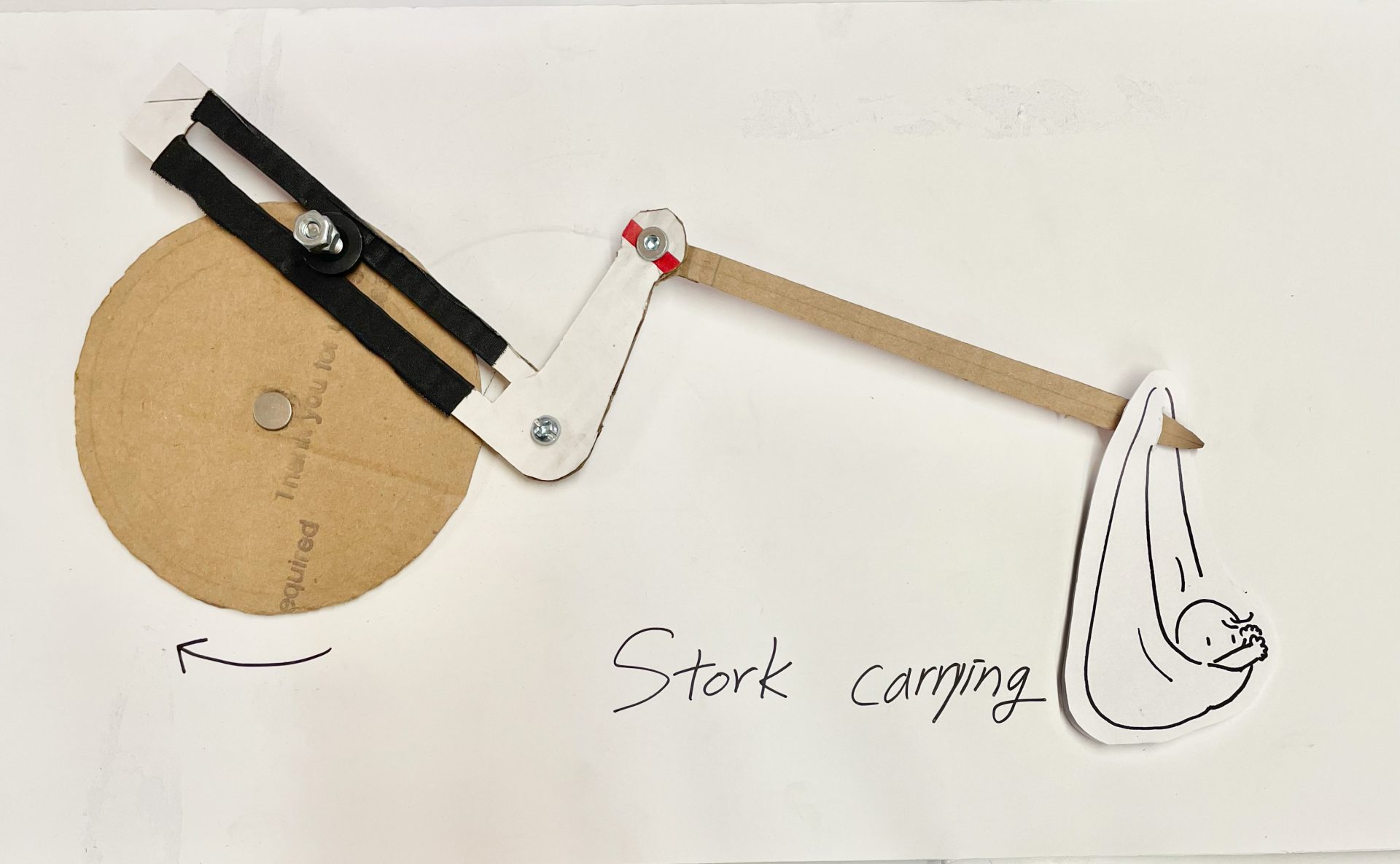
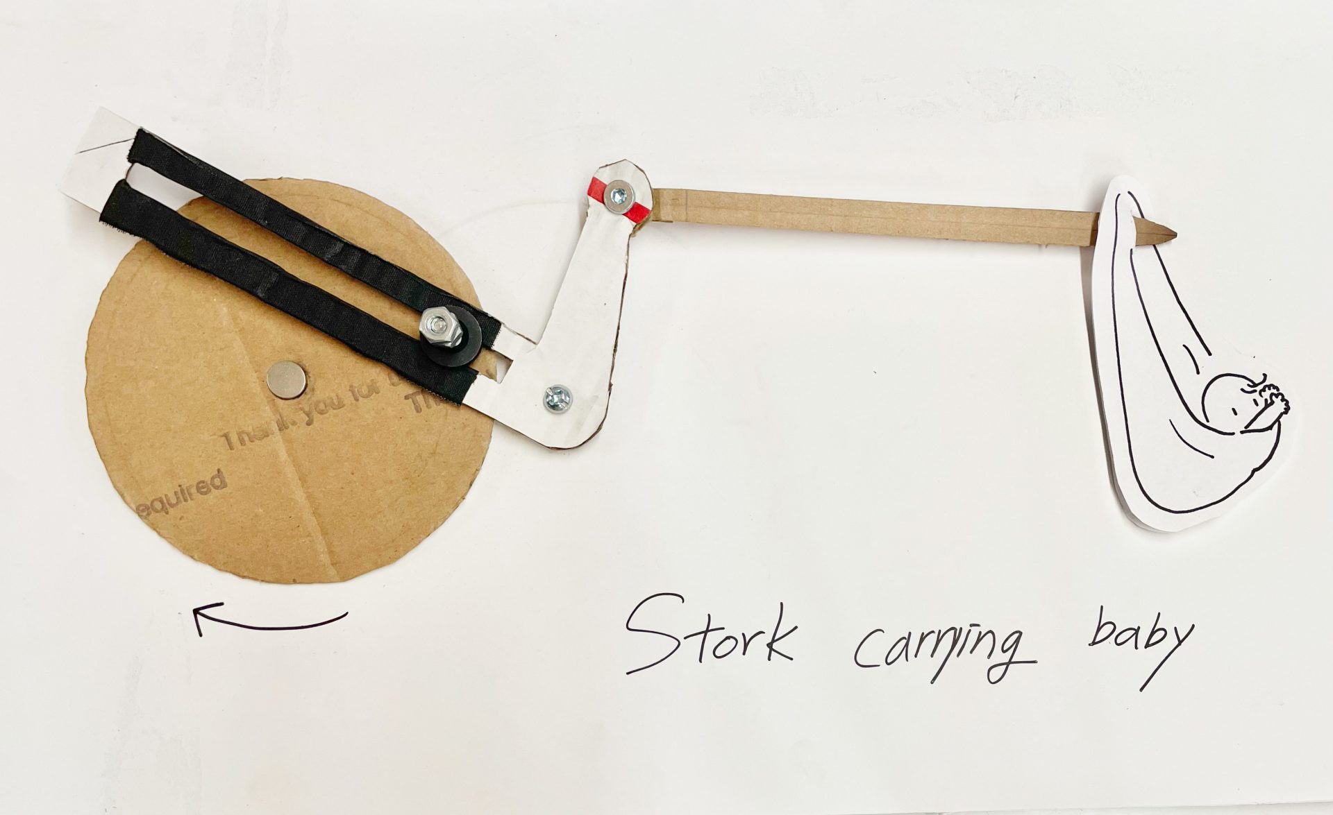
Prototype
Once assembled, the elbow-lever looked like a stork, so I tried adding a ‘baby’ component to the end, just like in the story “Stork carrying a baby”.