Midterm Process (Jiyou, Jenn and Amelia)
After testing the Heart rate sensor several times, we can check the range of rates between around 80~120.
In the shop, there are 2 kinds of pulse sensors: black(unknown brand) and red(Sparkfun)
The next step will be to connect the sensor to 4 servo motors.
What we should be concerned about is:
- How many Amp we need for servo motors
- How to decide whether to divide each sensor value by 3 parts with heart rates(Low/Mid/High)
/*
Heart beat plotting!
By: Nathan Seidle @ SparkFun Electronics
Date: October 20th, 2016
https://github.com/sparkfun/MAX30105_Breakout
Shows the user's heart beat on Arduino's serial plotter
Instructions:
1) Load code onto Redboard
2) Attach sensor to your finger with a rubber band (see below)
3) Open Tools->'Serial Plotter'
4) Make sure the drop down is set to 115200 baud
5) Checkout the blips!
6) Feel the pulse on your neck and watch it mimic the blips
It is best to attach the sensor to your finger using a rubber band or other tightening
device. Humans are generally bad at applying constant pressure to a thing. When you
press your finger against the sensor it varies enough to cause the blood in your
finger to flow differently which causes the sensor readings to go wonky.
Hardware Connections (Breakoutboard to Arduino):
-5V = 5V (3.3V is allowed)
-GND = GND
-SDA = A4 (or SDA)
-SCL = A5 (or SCL)
-INT = Not connected
The MAX30105 Breakout can handle 5V or 3.3V I2C logic. We recommend powering the board with 5V
but it will also run at 3.3V.
*/
#include <Wire.h>
#include "MAX30105.h"
MAX30105 particleSensor;
void setup()
{
Serial.begin(115200);
Serial.println("Initializing...");
// Initialize sensor
if (!particleSensor.begin(Wire, I2C_SPEED_FAST)) //Use default I2C port, 400kHz speed
{
Serial.println("MAX30105 was not found. Please check wiring/power. ");
while (1);
}
//Setup to sense a nice looking saw tooth on the plotter
byte ledBrightness = 0x1F; //Options: 0=Off to 255=50mA
byte sampleAverage = 8; //Options: 1, 2, 4, 8, 16, 32
byte ledMode = 3; //Options: 1 = Red only, 2 = Red + IR, 3 = Red + IR + Green
int sampleRate = 100; //Options: 50, 100, 200, 400, 800, 1000, 1600, 3200
int pulseWidth = 411; //Options: 69, 118, 215, 411
int adcRange = 4096; //Options: 2048, 4096, 8192, 16384
particleSensor.setup(ledBrightness, sampleAverage, ledMode, sampleRate, pulseWidth, adcRange); //Configure sensor with these settings
//Arduino plotter auto-scales annoyingly. To get around this, pre-populate
//the plotter with 500 of an average reading from the sensor
//Take an average of IR readings at power up
const byte avgAmount = 64;
long baseValue = 0;
for (byte x = 0 ; x < avgAmount ; x++)
{
baseValue += particleSensor.getIR(); //Read the IR value
}
baseValue /= avgAmount;
//Pre-populate the plotter so that the Y scale is close to IR values
for (int x = 0 ; x < 500 ; x++)
Serial.println(baseValue);
}
void loop()
{
Serial.println(particleSensor.getIR()); //Send raw data to plotter
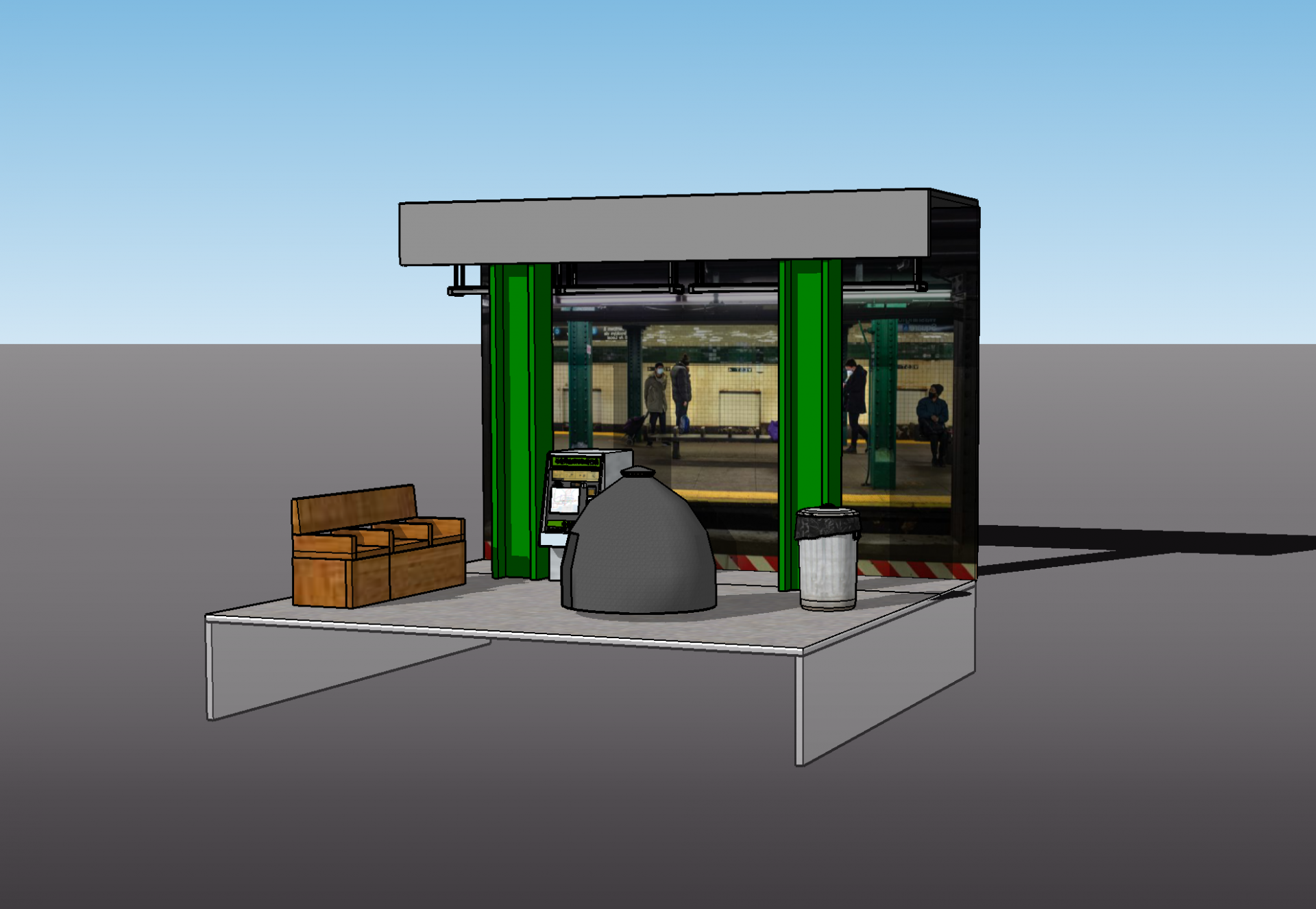
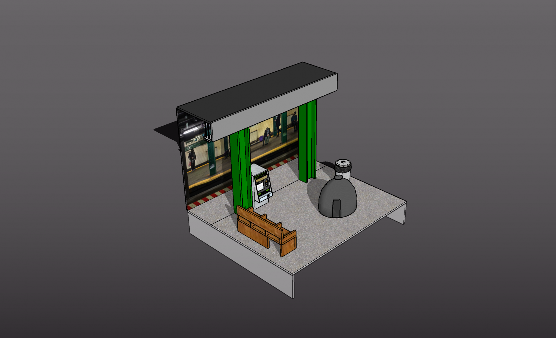
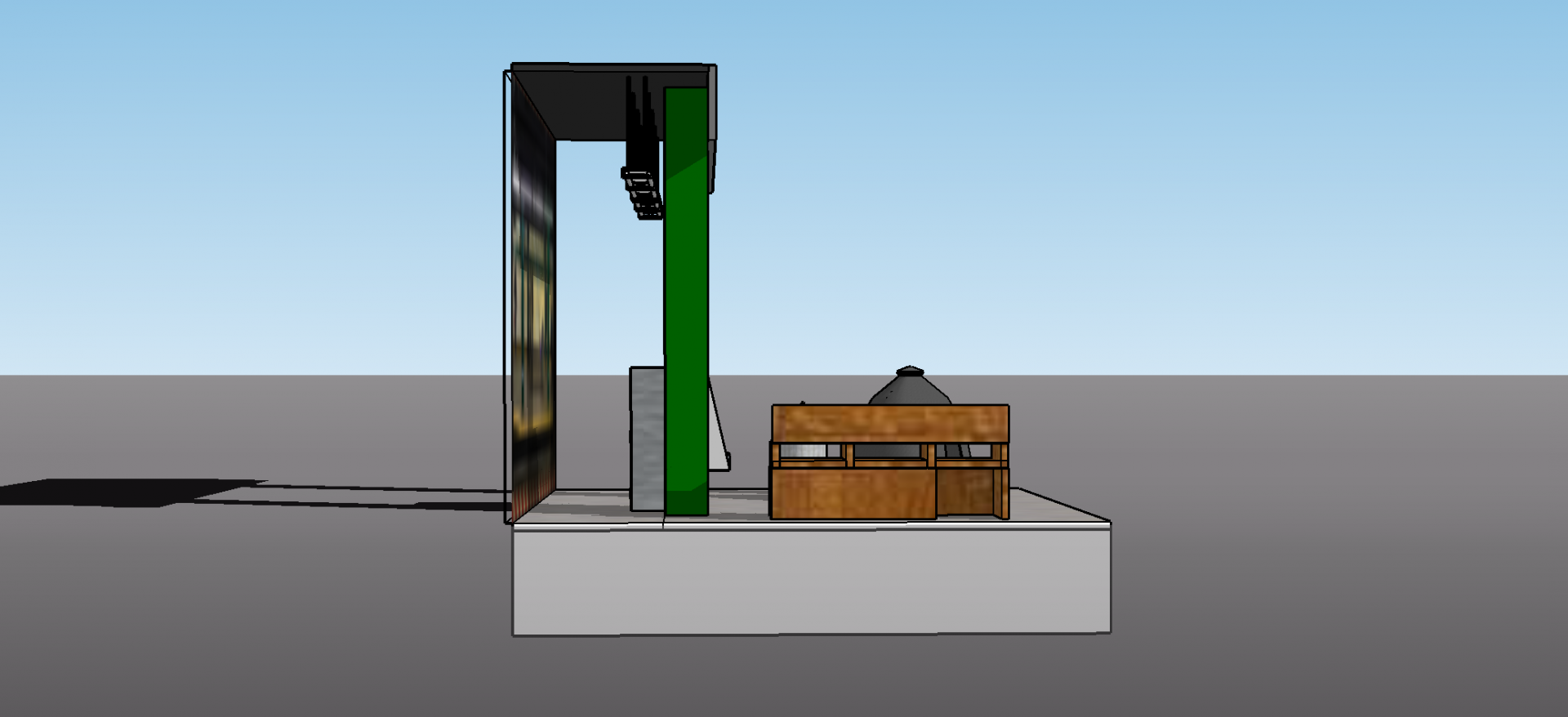
}These screenshots are modeling the installation where the sensors and outputs will be installed.
Lab: Using a Transistor to Control High Current Loads with an Arduino
const int transistorPin = 9;    // connected to the base of the transistor

 void setup() {
   // set  the transistor pin as output:
   pinMode(transistorPin, OUTPUT);
 }

 void loop() {
   digitalWrite(transistorPin, HIGH);
   delay(1000);
   digitalWrite(transistorPin, LOW);
   delay(1000);
 }
The Motor is on and off every second with this code (just like the blink sketch)
Program the microcontroller
The code below the video, potentiometer controls the speed of the motor.
const int transistorPin = 9; // connected to the base of the transistor
void setup() {
// set the transistor pin as output:
pinMode(transistorPin, OUTPUT);
}
void loop() {
// read the potentiometer:
int sensorValue = analogRead(A0);
// map the sensor value to a range from 0 - 255:
int outputValue = map(sensorValue, 0, 1023, 0, 255);
// use that to control the transistor:
analogWrite(transistorPin, outputValue);
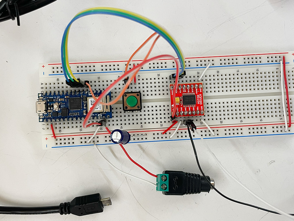
}Lab: DC Motor Control Using an H-Bridge
Arduino Nano connected to a motor driver to control a DC motor.
void setup() {
// set the switch as an input:
pinMode(switchPin, INPUT);
// set all the other pins you're using as outputs:
pinMode(motor1Pin, OUTPUT);
pinMode(motor2Pin, OUTPUT);
pinMode(pwmPin, OUTPUT);
// set PWM enable pin high so that motor can turn on:
digitalWrite(pwmPin, HIGH);
}
void loop() {
// if the switch is high, motor will turn on one direction:
if (digitalRead(switchPin) == HIGH) {
digitalWrite(motor1Pin, LOW); // set leg 1 of the motor driver low
digitalWrite(motor2Pin, HIGH); // set leg 2 of the motor driver high
}
// if the switch is low, motor will turn in the other direction:
else {
digitalWrite(motor1Pin, HIGH); // set leg 1 of the motor driver high
digitalWrite(motor2Pin, LOW); // set leg 2 of the motor driver low
}
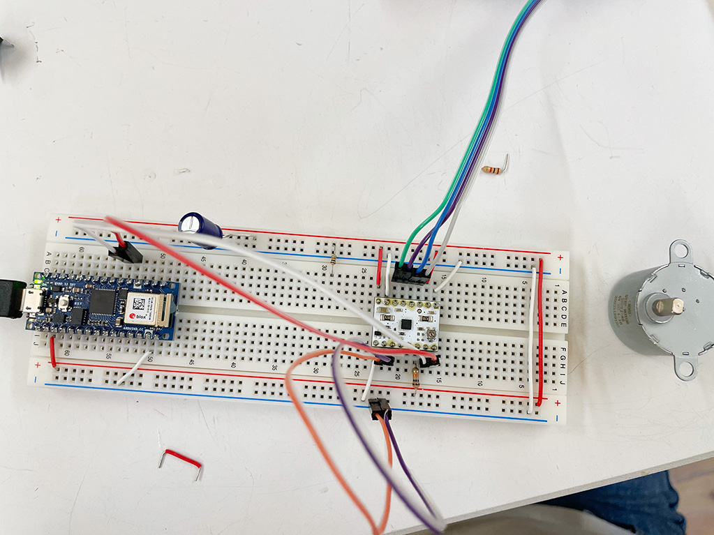
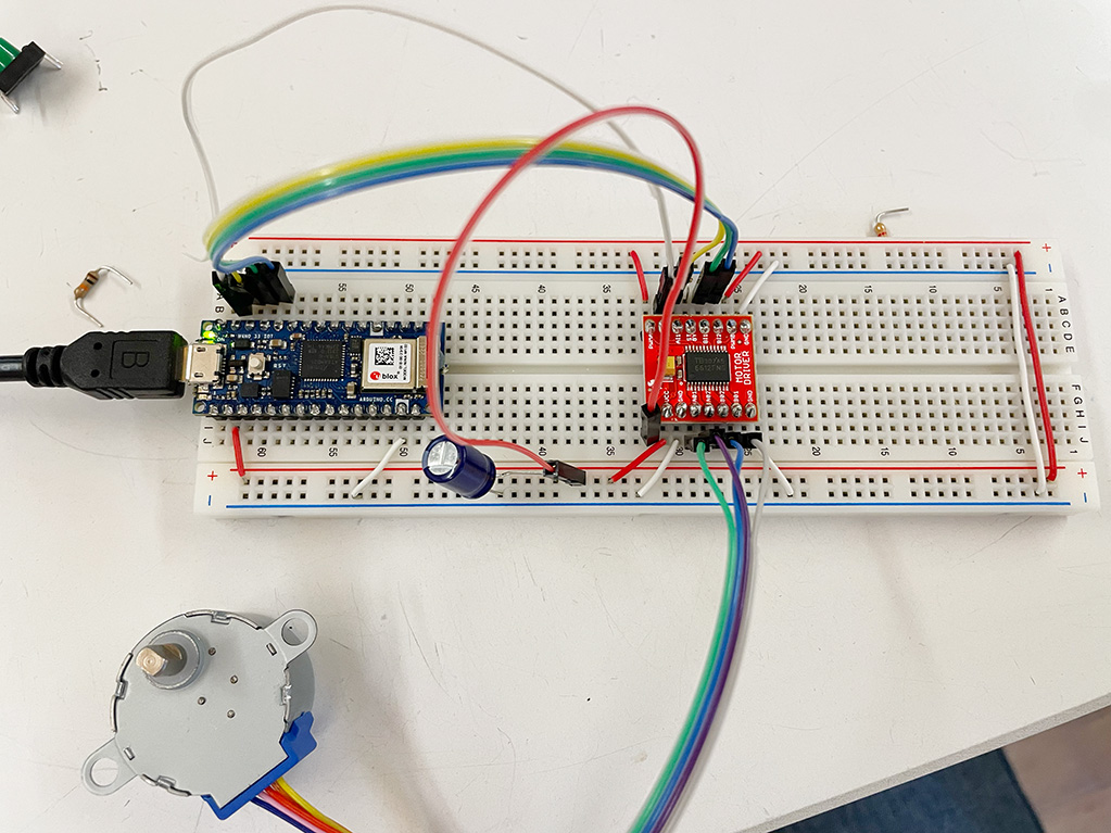
}Lab: Controlling a Stepper Motor With an H-Bridge
#include "Stepper.h"

const int stepsPerRevolution = 512;

// initialize the stepper library on pins 8 through 11:
Stepper myStepper(stepsPerRevolution, 8,9,10,11);

int stepCount = 0;       // number of steps the motor has taken

void setup() {
  // initialize the serial port:
  Serial.begin(9600);
}

void loop() {
  // step one step:
  myStepper.step(1);
  Serial.print("steps:" );
  Serial.println(stepCount);
  stepCount++;
  delay(500);
}#include "Stepper.h"
const int stepsPerRevolution = 512;
// initialize the stepper library on pins 8 through 11:
Stepper myStepper(stepsPerRevolution, 8,9,10,11);
void setup() {
// set the speed at 60 rpm:
myStepper.setSpeed(10);
// initialize the serial port:
Serial.begin(9600);
}
void loop() {
// step one revolution in one direction:
Serial.println("clockwise");
myStepper.step(stepsPerRevolution);
delay(500);
// step one revolution in the other direction:
Serial.println("counterclockwise");
myStepper.step(-stepsPerRevolution);
delay(500);
}
Lab: Controlling a Stepper Motor With a Step and Direction Driver